Keyboard switches are at the heart of one of the most used human input devices, the keyboard. They are produced in a number of different form factors and styles. This report will serve as an overview with a focus on mechanical switches.
Description
Keyswitches are at the heart of one of the most used human input devices, the keyboard. They are produced in a number of different form factors and styles.
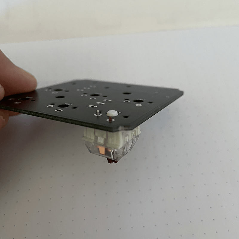
The mechanical keyboard Switch: when the keycap is depressed the the plates inside the keyboard Switch make contact, the keyboard Switch is connected to a PCB located below it, which in turn completes a circuit sending an electrical signal to the device resulting in a predetermined action. These keyboard Switches preform the same type of action that a momentary, non-latching, switch preforms. The result is a temporary state change.
The rubber dome switch: when the keycap is depressed the living hinge collapses allowing the conductive pad to make contact with the PCB, completes the circuit and sends an electrical signal to the device resulting in a predetermined action. These keyboard Switches also preform the same type of action that a momentary, non-latching, switch preforms. The result is a temporary state change.

Definitions
Terms frequently used when referring to keyboard Switches.
- Clicky: refers to the sound made when the swatch is pressed
- Tactile: refers to a noticeable bump or shift when pressing the switch
- Quiet: low noise but still precipitable
- Linear: no bump or shift, but has noticeable resistance
- Silent: no precipitable sound, usually only membrane or rubber dome
- Centinewton: the force measurement for actuation
- Actuation Force: the amount of pressure need to move depress the switch
- Actuation Distance: amount of movement before contact is made
Typical Applications
The keyboard Switch is first and foremost designed to be use in keyboards. Most have a fast response time and because of the PCB and firmware used often times multiple keypresses from different keys at the same time still register. Although keyboard Switches are predominantly found in keyboards the possibilities for use in other areas is quite broad. There are some mice on the market that use these type of switches under the two main left and right buttons. Furthermore there are many different types of keyboard Switches in terms of feel clicky, quiet, tactile, and are also available with different actuation force.
Manufacturer Info
Link to folder containing all the datasheets for a number of common keyboard Switches. A great resource for a large database of switches can be found at this github https://github.com/keyboardio/keyswitch_documentation/tree/master/datasheets
- Cherry MX Red
- Cherry MX Black
- Cherry MX Brown
- Gateron
- Kalih Jade
- Kalih Purple
- Dow Corning B6650 Rubber Dome
Electrical Characteristics
Basic information from compiled datasheets, there are many different keyboard Switches but they all have the same basic electrical specifications. The points below have been aggregated from more than 20 datasheets.
- Switching Voltage 12V AC/DC max – 2V AC/DC min
- Switching Current 10mA AC/DC max – 10µA min
- Insulation Resistance 100MΩ/DC 500V
- Withstand Voltage 100V AC 1 minute
- Dielectric Strength 500V 50Hz
- Actuation Force 45cN-95cN
Physical Characteristics

Vendor and Module Info
Each keyboard Switch has a specific way to interface with a PCB, however no keyboard Switch is packaged with a PCB. It is the responsibility of the designer to create or acquire a PCB with the appropriate interface for the chosen keyboard Switch. A few common manufactures include Cherry, Kailh, Matias, Torpe, Gateron, and Outemu. By for the most used standard is MX, developed by Cherry but adopted by many of the aforementioned manufactures.
Sparkfun makes a single switch breakout board, useful for prototyping or for using the switch in a non-traditional application. It can be found here https://www.sparkfun.com/products/13773?_ga=2.14326772.291551882.1619464014-774819918.1618316946
Design Considerations
There are many factors regarding the use of keyboard Switches, switch feel is the most important characteristic. Almost every keyboard Switch produced will have a written description of how the switch feels when being used. The terms that are most commonly used are as follows, these can also be found in the section above titled “Definitions”; clicky, tactile, linear, and silent. These terms can be used in conjunction with each other i.e. clicky + tactile. The second factor to consider is actuation force usably given in centinewton(cN) which is a decimal fraction of the SI unit for force KgF.
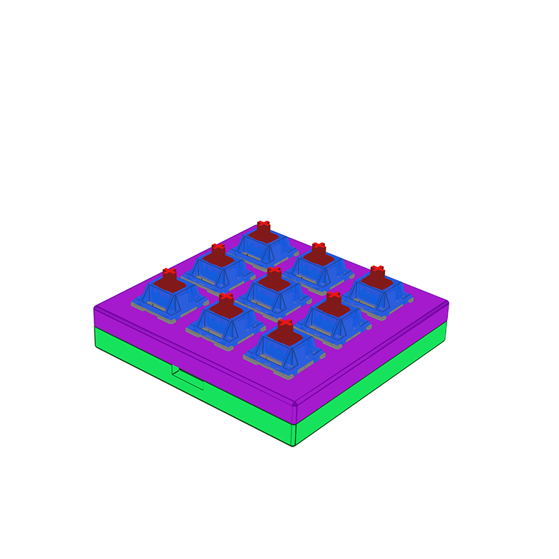
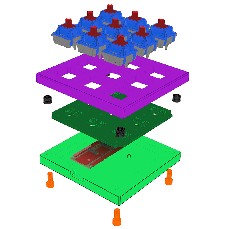
Custom housing is always almost necessary, utilizing the datasheets for dimensions and interface points is crucial for proper functionality. Prototyping can be difficult, keep in mind that this switch functions the same as a push-button momentary switch allowing the use of a breadboard to test the circuit before committing to a permanent solution.


Strengths and Weaknesses
The major weakness of all keyboard Switches on the market today is the need for a specific PCB layout and the need for an appropriate housing. The size of most keyboard Switches has been somewhat standardized over the past few years however, the PCB layout and interface have not. That being said, again, by for the most used standard is MX, developed by Cherry but adopted by many of the aforementioned manufactures.
Since these switches are mechanical there are moving parts, this means they will eventually wear out. Although most mechanical keyboard switches claim to have 50-100 million actuations.
Example Circuit Schematic
keyboard Switches are almost always used in multiples the circuit schematic below has 3 x 3 matrix resulting nine switch positions. To read all the switches row/column scanning is used, see “Example Microcontroller Code” for code example. Note the inclusion of a diode at each switch, this is needed to reduce the likelihood of ghosting where a key that hasn’t been pressed is recorded or a missed key press. The diode stops the signal from traveling “backwards” and giving a false reading.


Example Microcontroller Code
For this example there are nine switches, normally this would take nine input pins to control, for this reason row-column scanning is used. This allows nine switches to take only six pins, three rows and three columns. This becomes even more important when adding more keys, for instance a standard full-size keyboard has 104 keys, the input can be accomplished with the use of just 22 pins, 11 for the rows and 11 for the columns.
Here are two examples of code for row-column scanning, it’s also know as a matrix. The fist example makes use of the Keypad.h library which can be found here https://github.com/Chris–A/Keypad/tree/master/src. In current versions of the Arduino IDE you can search of “Keypad.h” in the library manager and install it directly from there.
The second example is basically what happens behind the scene in the Keypad.h library. The code can be found here https://www.baldengineer.com/arduino-keyboard-matrix-tutorial.html.
<include Keypad.h>;
const byte ROWS = 3;
const byte COLS = 3;
char keys[ROWS][COLS] = {
{'1', '2', '3'},
{'4', '5', '6'},
{'7', '8', '9'}
};
byte rowPins[ROWS] = {9, 8, 7};
byte colPins[COLS] = {5, 4, 3};
Keypad keypad = Keypad(makeKeymap(keys), rowPins, colPins, ROWS, COLS);
void setup(){
Serial.begin(9600);
}
void loop(){
char key = keypad.getKey();
if (key != NO_KEY){
Serial.println(key);
}
}
// Keyboard Matrix Tutorial Example
// baldengineer.com
// CC BY-SA 4.0

// JP1 is an input
byte rows[] = {2,3,4};
const int rowCount = sizeof(rows)/sizeof(rows[0]);

// JP2 and JP3 are outputs
byte cols[] = {8,9,10};
const int colCount = sizeof(cols)/sizeof(cols[0]);

byte keys[colCount][rowCount];

void setup() {
    Serial.begin(115200);

    for(int x=0; x<rowCount; x++) {
        Serial.print(rows[x]); Serial.println(" as input");
        pinMode(rows[x], INPUT);
    }

    for (int x=0; x<colCount; x++) {
        Serial.print(cols[x]); Serial.println(" as input-pullup");
        pinMode(cols[x], INPUT_PULLUP);
    }

}

void readMatrix() {
    // iterate the columns
    for (int colIndex=0; colIndex < colCount; colIndex++) {
        // col: set to output to low
        byte curCol = cols[colIndex];
        pinMode(curCol, OUTPUT);
        digitalWrite(curCol, LOW);

        // row: interate through the rows
        for (int rowIndex=0; rowIndex < rowCount; rowIndex++) {
            byte rowCol = rows[rowIndex];
            pinMode(rowCol, INPUT_PULLUP);
            keys[colIndex][rowIndex] = digitalRead(rowCol);
            pinMode(rowCol, INPUT);
        }
        // disable the column
        pinMode(curCol, INPUT);
    }
}

void printMatrix() {
    for (int rowIndex=0; rowIndex < rowCount; rowIndex++) {
        if (rowIndex < 10)
            Serial.print(F("0"));
        Serial.print(rowIndex); Serial.print(F(": "));

        for (int colIndex=0; colIndex < colCount; colIndex++) {
            Serial.print(keys[colIndex][rowIndex]);
            if (colIndex < colCount)
                Serial.print(F(", "));
        }
        Serial.println("");
    }
    Serial.println("");
}

void loop() {
    readMatrix();
    if (Serial.read()=='!')
        printMatrix();
}
Citations
- https://deskthority.net/wiki/Category:Keyboard_switches Incredible resource for all thing related to keyboard switches and other Human Input Devices (HID)
- https://www.keychatter.com/#
- https://www.mechanical-keyboard.org/switch-types/
- http://homemadehardware.com/ PCB making tutorial can be found here
- http://www.retrobuiltgames.com/the-build-page/macro-keyboard-v2-0/
- https://github.com/datulab/arduino-keyboard
- https://www.baldengineer.com/arduino-keyboard-matrix-tutorial.html great overall explanation on how row-column scanning works, this link has one of the example code usage from earlier in this post.
- https://www.dribin.org/dave/keyboard/one_html/
- https://www.arduino.cc/en/Tutorial/BuiltInExamples/RowColumnScanning this example is from the Arduino IDE, it is setup for LEDs but does a good job of explaining what row-column scanning is and how it works.
- https://jlcpcb.com/ easy to use manufacturer for custom PCBs
- https://www.sparkfun.com/products/7836 Square rubber dome switch
- https://www.sparkfun.com/products/9277 Breakout PCB for 2×2 square rubber dome button
- https://itp.nyu.edu/classes/tangible-interaction/2018/02/21/silicone-button-pad/
- https://github.com/keyboardio/keyswitch_documentation/tree/master/datasheets github with almost all datasheets you could ever want.
- https://learn.sparkfun.com/tutorials/cherry-mx-switch-breakout-hookup-guide Sparkfun guide for prototyping with the breakout board module


